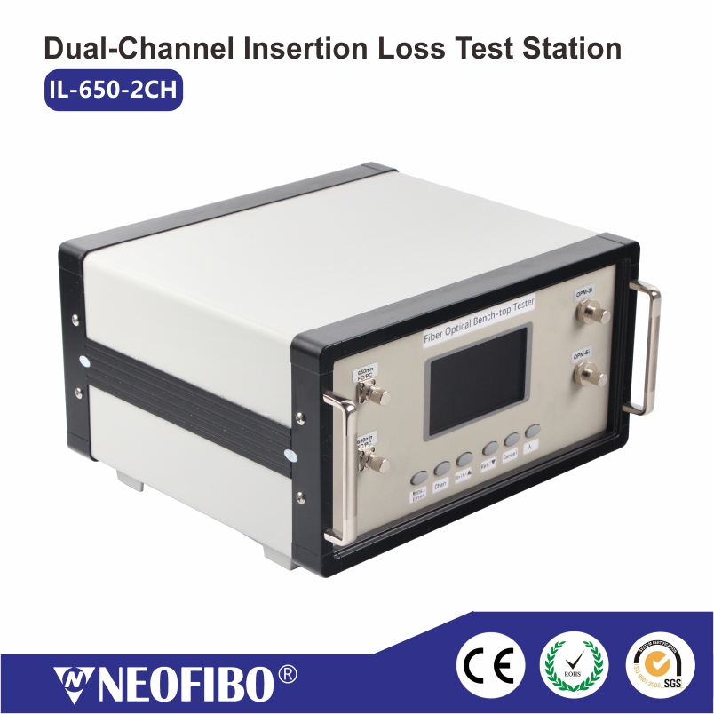
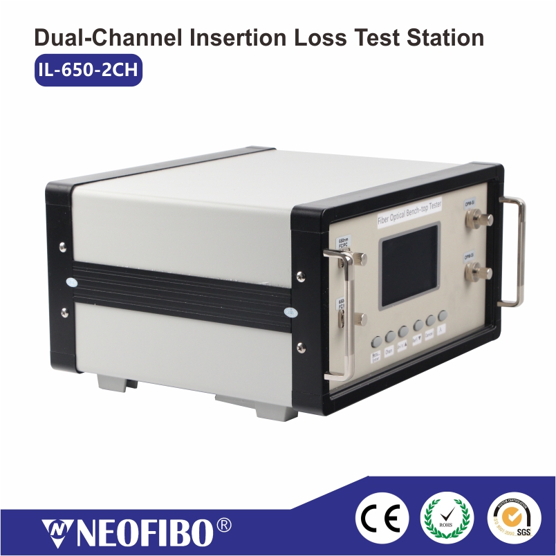
Description:
It is used to measure the access loss of optical fiber at 650nm wavelength, and is commonly used for testing the optical index of plastic fiber or special quartz fiber.
Main Features.
- Dual-channel light source with an output power of 1+/-0.2mW;
- Dual-channel power meter, effectively measuring the loss of access fiber or link;
- Dedicated to HFBR series jumper insertion loss measurement;
- Can also be used for special quartz fiber optical fiber harness insertion loss measurement;
- Convenient for wire harness manufacturers to digitally manage the optical indicators of the harness to ensure product qualification rate.
Technical Parameters:
| Model | IL-650-2CH |
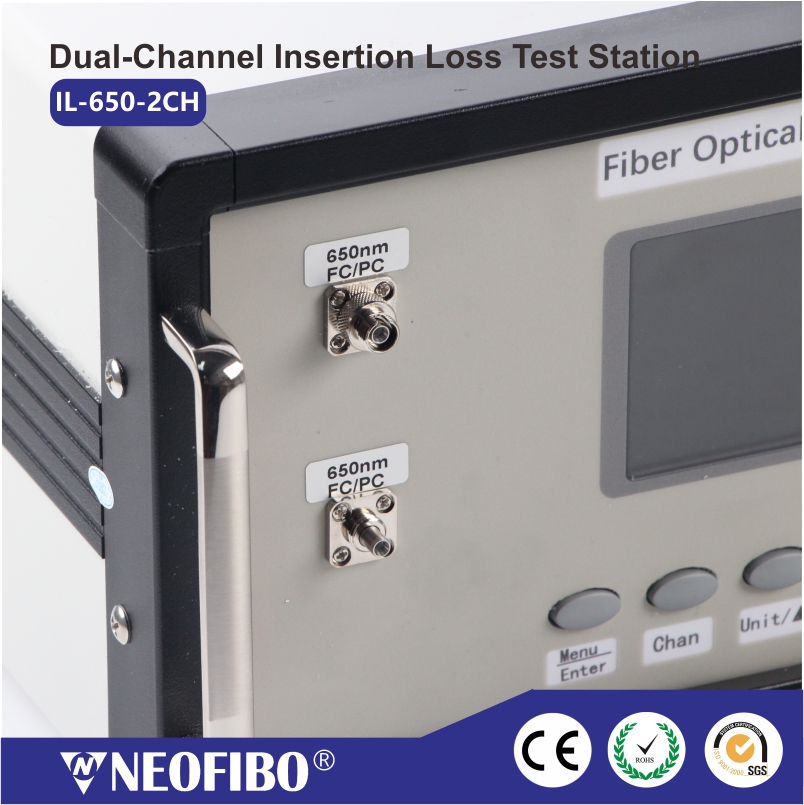
| Light source wavelength | 650nm |
| Light source power | 1+/-0.2mW |
| Optical power meter wavelength | 650nm |
| Measurement range (dBm) | -30~+3 |
| Uncertainties | ±3% |
| Display resolution | Linearity: 2 decimal places; Relative Measurement: 0.01dB |
| light-emitting device (LED) | LD |
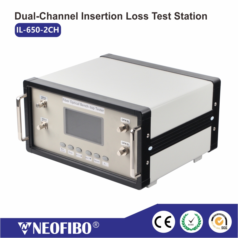
Functional Description:
| Markings | Function |
| Switching Wavelengths | |
| Chan | Switching channels (dual-channel exclusive function) |
| UNIT/▲ | Measurement unit switching |
| REF/▼ | Setting the relative power value and entering the relative value measurement mode |
| Menu/Enter | Access to the menu screen |
| Cancel | Deselect or opt out |
Instructions for use:
- Change the wavelength value: Press λ to enter the change wavelength switching.
- Power display switching: Press UNIT/▲ to switch the unit between dBm\mw\uw.
- Relative power zeroing (loss test):
Zero the optical path insertion loss before measurement. Insert the end of the marker line into the optical power meter interface and press the REF key. Use the standard flange to connect the end of the marker with the measured end (start end) of the tested patch cord, and the other end (end) of the tested patch cord is inserted into the interface of the optical power meter. At this time, the differential loss measurement in the insertion loss display area is the insertion loss value at the beginning end of the patch cord under test.
Maintenance and care:
- The optical power meter should work without obvious vibration.
- Keep the sensor end face clean, do not use unclean, non-standard optical connectors.
- When the optical power meter is not in use, please cover the dust cap.
- Plug and unplug the optical connector carefully.
- When cleaning the sensor surface, please use lens paper, add cleaning solution and then gently inserted along the circumference of the wipe.
- Hold and put gently, to prevent the optical power meter fall, collision.